Firmware Update
SANPO Official Firmware Update
Preparation
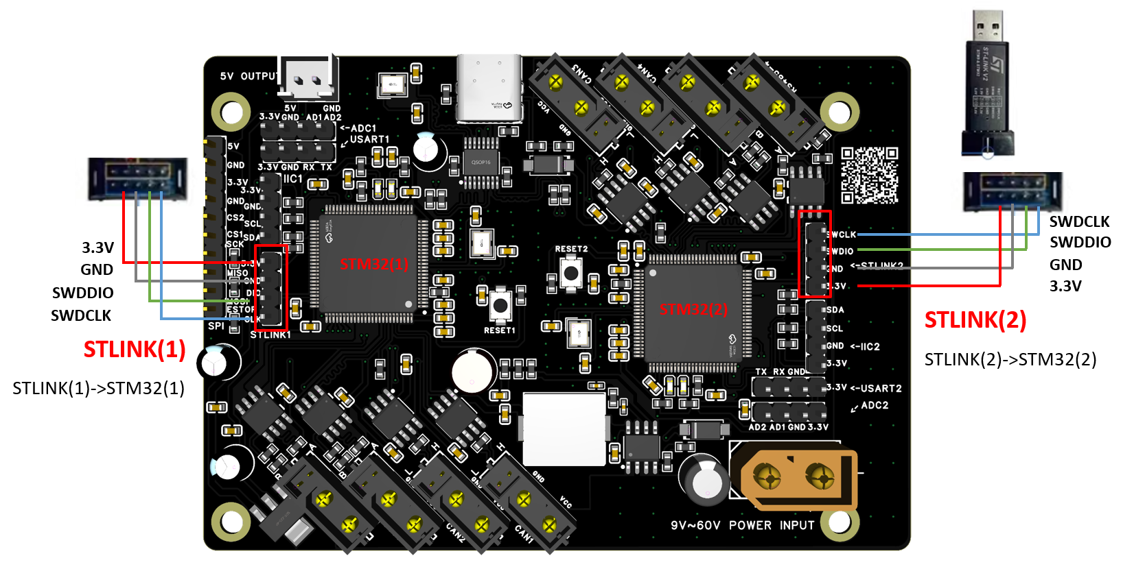
Prepare an STLINK (SWD) programmer and connect the board STLINK interface to your PC.
The board has two STLINK interfaces for the two STM32F407 chips. Update each chip separately. Note: board must be powered via USB, and the on-board 3.3V pin is configured as an output voltage.
Update Steps
Install tools
Download and install the official ST flashing tool: STM32CubeProgrammerGet firmware
Download the latest official firmware: sanpo_robot_spine_board_firmware-v4-latest.binFlash firmware
Disconnect the board external power supply and use STM32CubeProgrammer to flash the firmware to the board (flash the two chips separately).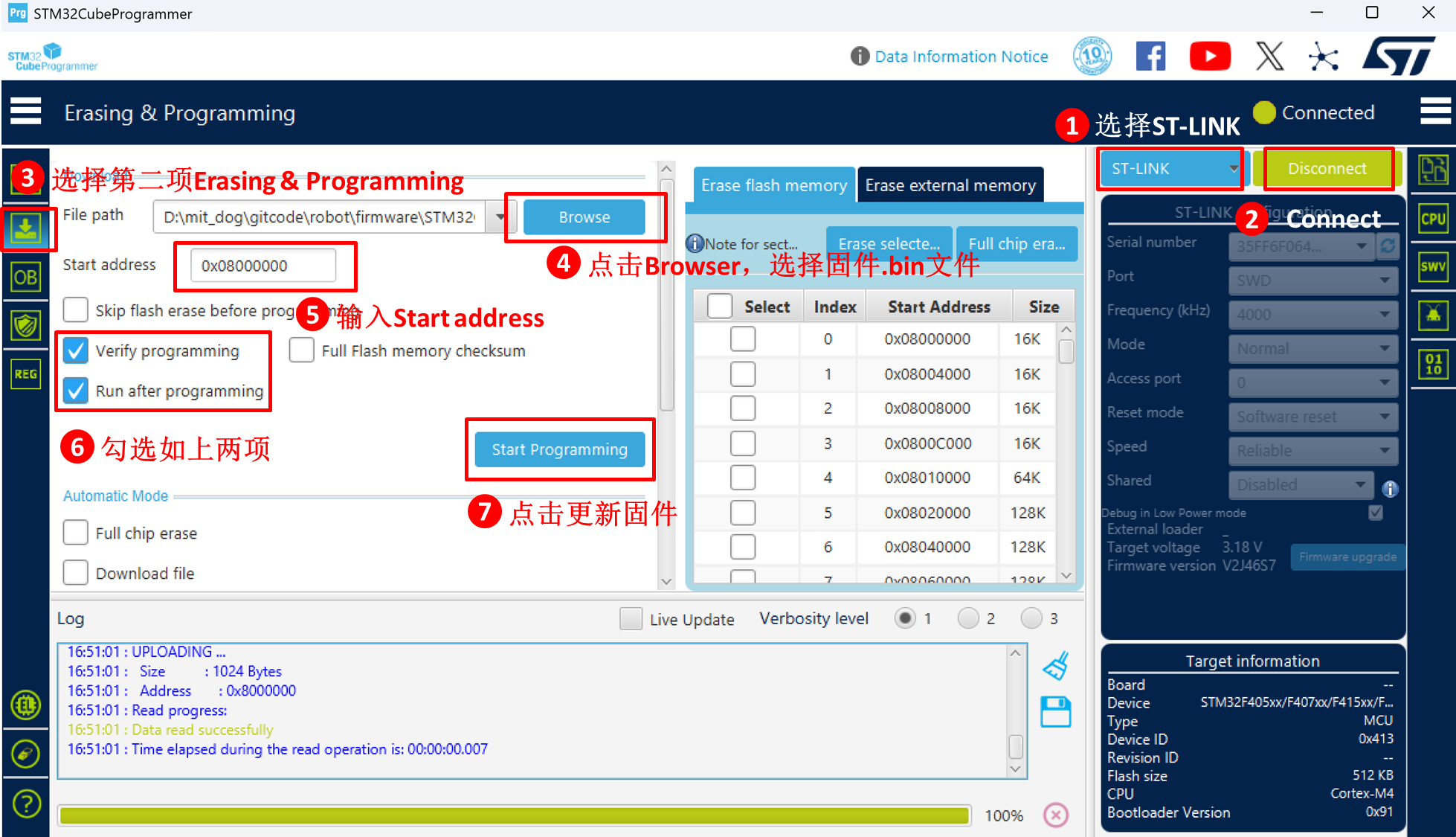
MIT Cheetah SPINE Firmware Update
Recommended approach: mbed studio project (download mbed-os.zip and extract it to the project folder).
Tip: Avoid nesting multiple
mbed-osdirectories or you may not findtargets. Recommended structure:mit_spine_mbed_studio/mbed-os/targets.
Update Steps
Install mbed studio.
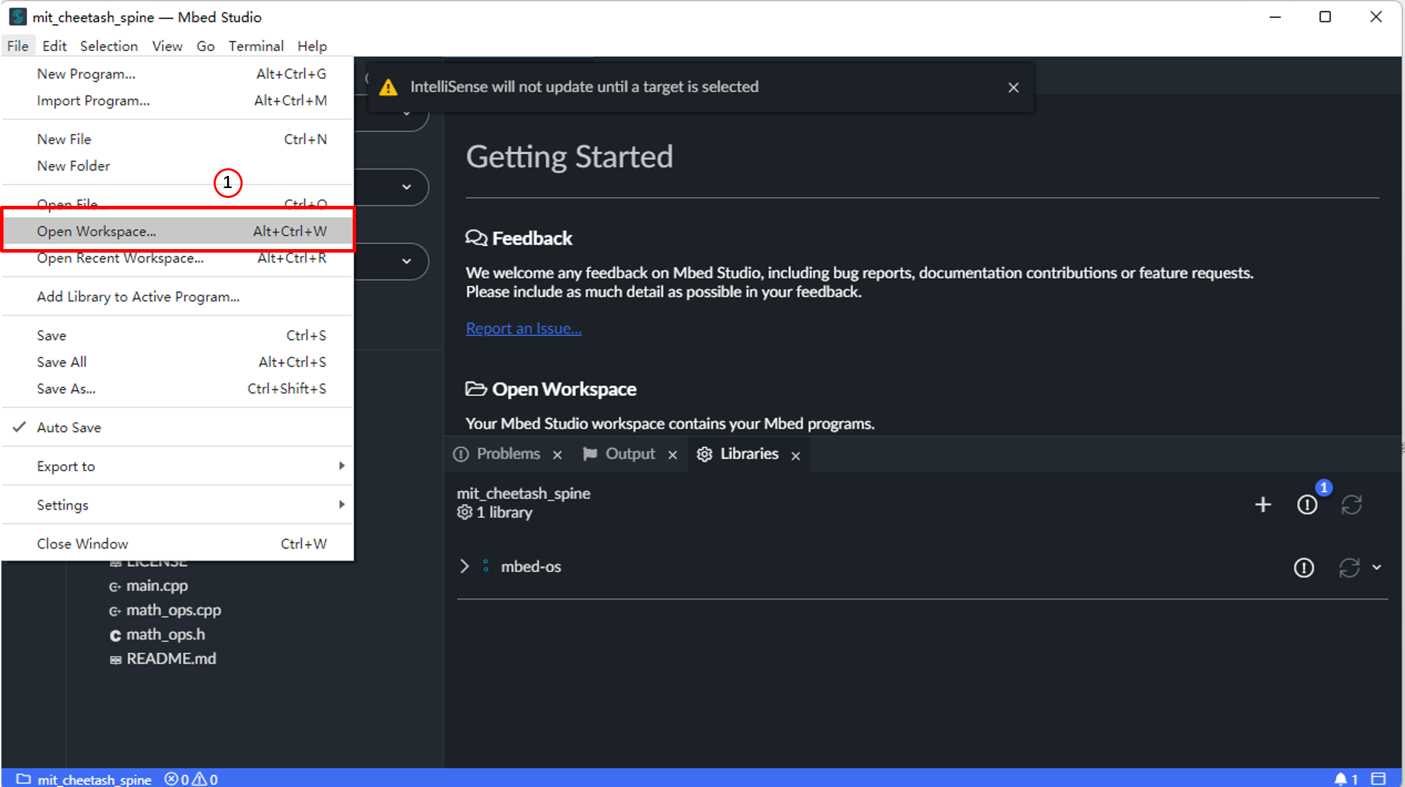
Open the MIT firmware source workspace.
Connect STLINK and select the target chip: STM32F407VETx.
Click Build program to compile and flash.
Also, if you use a Keil project, you still need to extract
mbed-os.zipinto the project folder and avoid nesting multiplembed-osdirectories.
Operation Images
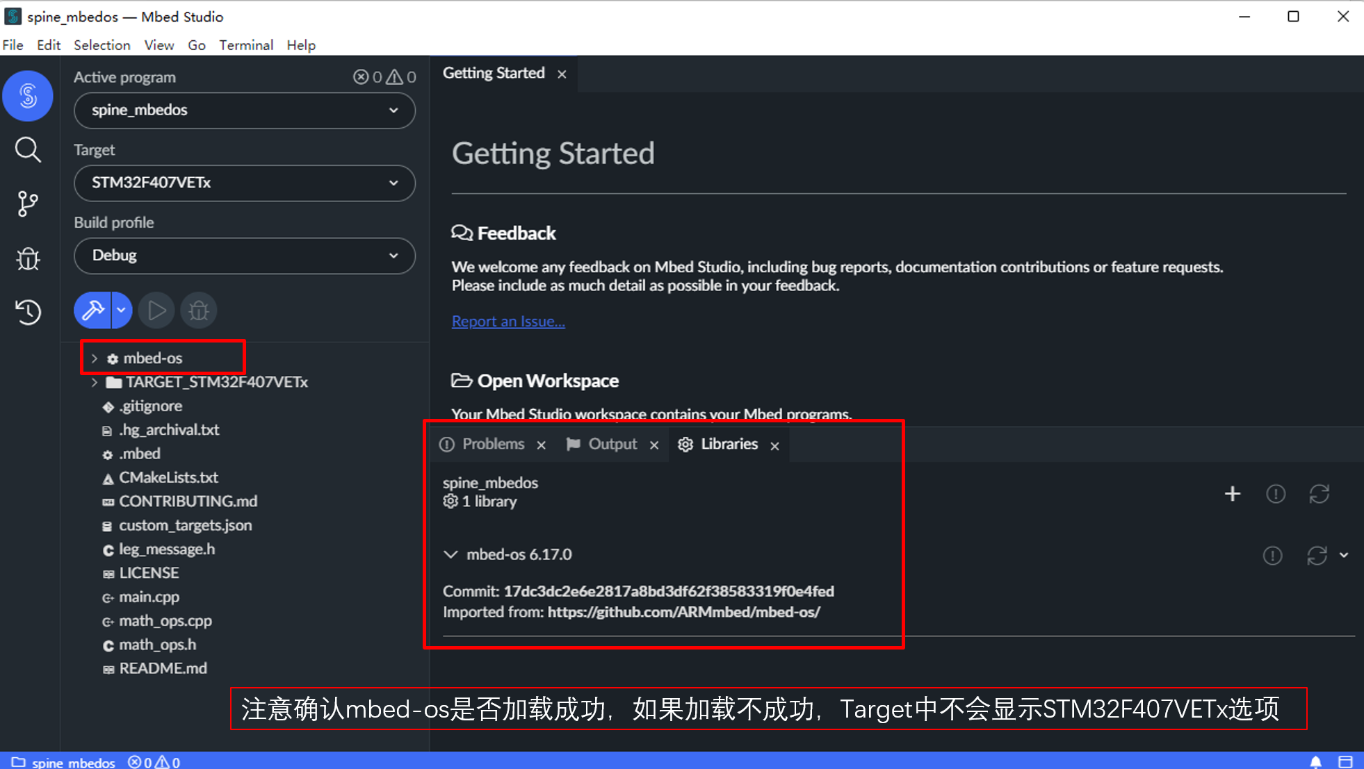
Step 1:
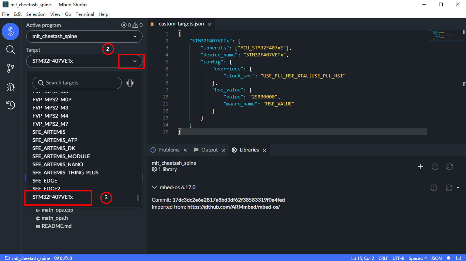
Step 2:
Step 3:
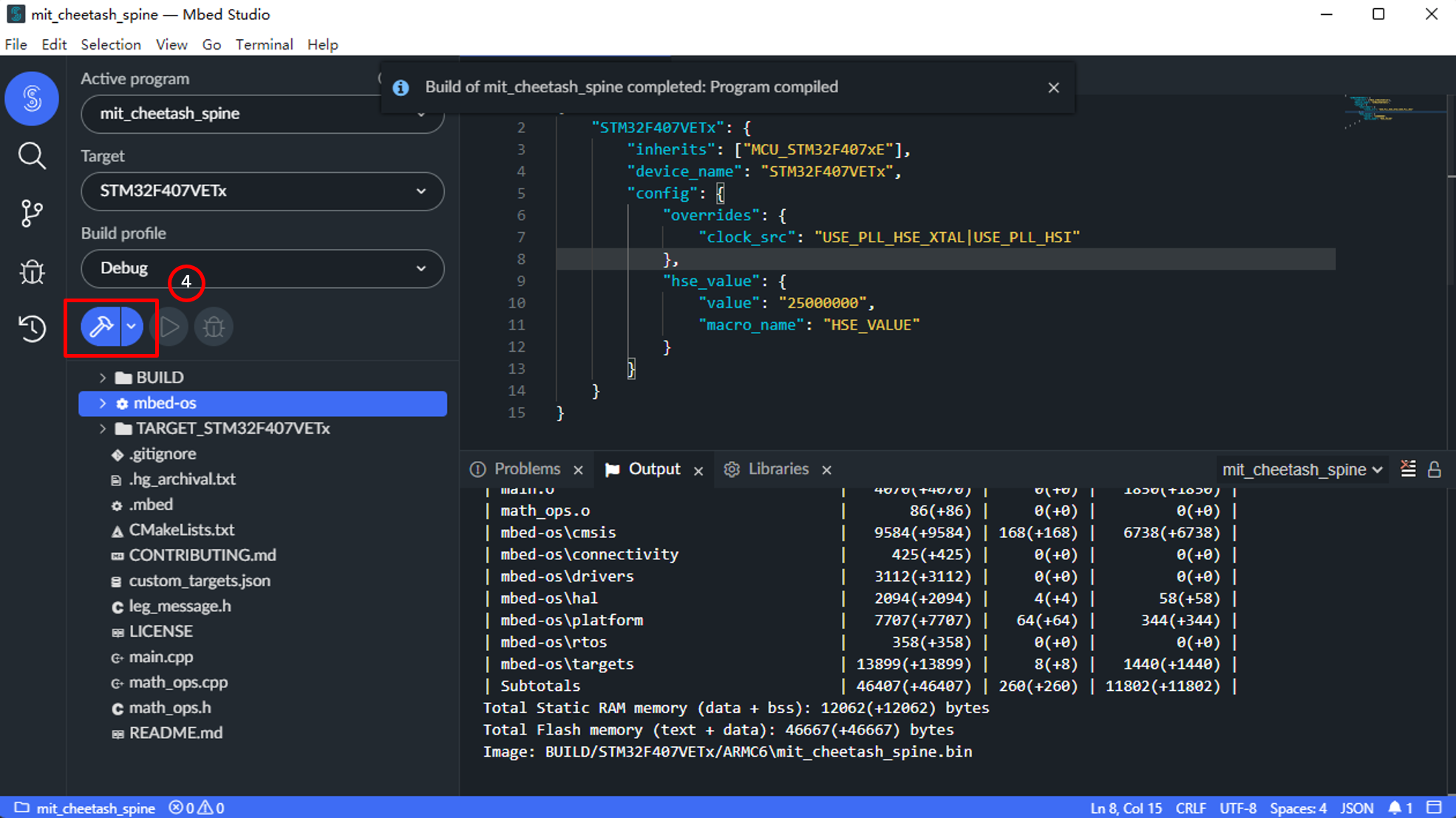
Step 4:
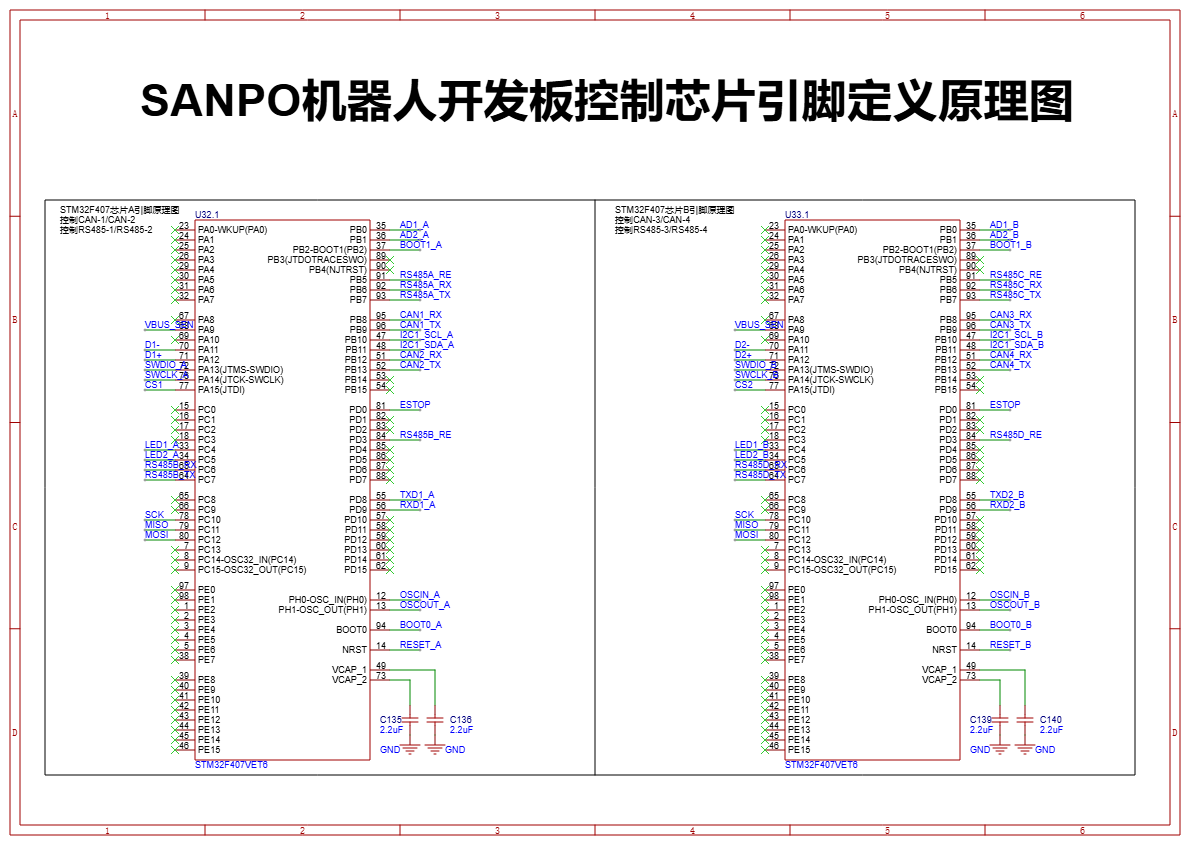
STM32 Pin Definitions
Chip 1: STM32F407(1)
Interface |
Pin |
STM32 Pin |
|---|---|---|
ADC Interface 1 |
AD1 |
PB0 |
ADC Interface 1 |
AD2 |
PB1 |
UART 1 |
TX |
PD8 |
UART 1 |
RX |
PD9 |
SPI Interface |
CS1 |
PA15 |
SPI Interface |
SCK |
PC10 |
SPI Interface |
MISO |
PC11 |
SPI Interface |
MOSI |
PC12 |
Reserved Interface |
ESTOP/RSDV |
PD0 |
IIC Interface 1 |
SCL |
PB10 |
IIC Interface 1 |
SDA |
PB11 |
SWD Debug 1 |
SWDIO |
PA13 |
SWD Debug 1 |
SWCLK |
PA14 |
RS485-2 |
RX |
PC6 |
RS485-2 |
TX |
PC7 |
RS485-1 |
RX |
PB6 |
RS485-1 |
TX |
PB7 |
CAN2 |
RX |
PB12 |
CAN2 |
TX |
PB13 |
CAN1 |
RX |
PB8 |
CAN1 |
TX |
PB9 |
Chip 2: STM32F407(2)
Interface |
Pin |
STM32 Pin |
|---|---|---|
ADC Interface 2 |
AD1 |
PB0 |
ADC Interface 2 |
AD2 |
PB1 |
UART 2 |
TX |
PD8 |
UART 2 |
RX |
PD9 |
SPI Interface |
CS2 |
PA15 |
SPI Interface |
SCK |
PC10 |
SPI Interface |
MISO |
PC11 |
SPI Interface |
MOSI |
PC12 |
Reserved Interface |
ESTOP/RSDV |
PD0 |
IIC Interface 2 |
SCL |
PB10 |
IIC Interface 2 |
SDA |
PB11 |
SWD Debug 2 |
SWDIO |
PA13 |
SWD Debug 2 |
SWCLK |
PA14 |
RS485-3 |
RX |
PB6 |
RS485-3 |
TX |
PB7 |
RS485-4 |
RX |
PC6 |
RS485-4 |
TX |
PC7 |
CAN3 |
RX |
PB8 |
CAN3 |
TX |
PB9 |
CAN4 |
RX |
PB12 |
CAN4 |
TX |
PB13 |
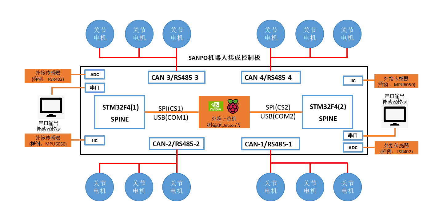
Hardware Architecture
Circuit Schematic