Get Started
The SANPO robot integrated controller board Standard Version is designed for robot joint motor control, bus communication, and sensor integration. It supports multiple host control methods including USB, SPI, and UART, is compatible with CAN / RS485 joint motor protocols, and provides offline execution, firmware update, and secondary development capabilities.
This page helps you quickly understand the standard board, hardware interfaces, connection methods, debugging tools, and the entry points for protocols and firmware.
Product Overview
Provides 4 independent CAN channels and 4 independent RS485 channels.
Supports a 6V~58V motor system power supply.
Supports control system power from USB, a 5V terminal, or host 5V GPIO.
Provides 6V~58V and 3.3V power outputs.
Suitable for mixed CAN / RS485 bus debugging, functional validation, and rapid integration.
Main Specifications
Item |
Parameter |
|---|---|
Processor |
Dual high-performance STM32 MCUs |
Control method |
USB / SPI / UART |
Device bus |
4 independent CAN + 4 independent RS485 |
Motor system power supply |
6V~58V |
Control system power supply |
USB, 5V terminal, host 5V GPIO |
Power output |
6V~58V / 3.3V |
Power transient pulse |
1.5kW peak, 93V clamping voltage |
Typical Use Cases
CAN / RS485 mixed-bus debugging.
Robot joint motor functional validation.
Prototype development and rapid integration.
Design Notes
During motor startup, emergency stop, and direction switching, the system may experience common-mode interference, ground potential fluctuation, regenerative energy, and transient pulses. The board provides transient power pulse handling capability up to a 1.5kW peak with 93V clamping voltage, covering common transient conditions in robot joint systems.
Main Capabilities
Dual high-performance STM32 MCU control architecture for multi-channel joint motor control.
Supports multiple host control inputs including USB, SPI, and UART.
Supports CAN / RS485 joint motor protocol access.
Supports offline execution and task scheduling for batch command download and standalone operation.
Supports IIC, ADC, and UART-based sensor expansion for attitude, pressure, and similar peripherals.
Supports firmware download, update, and secondary development through the SWD interface.
Compatible with the MIT Cheetah SPINE design approach.
Board Architecture
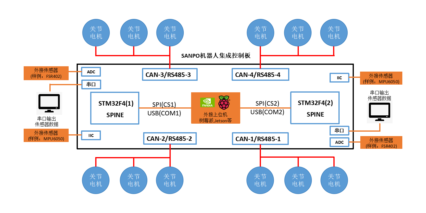
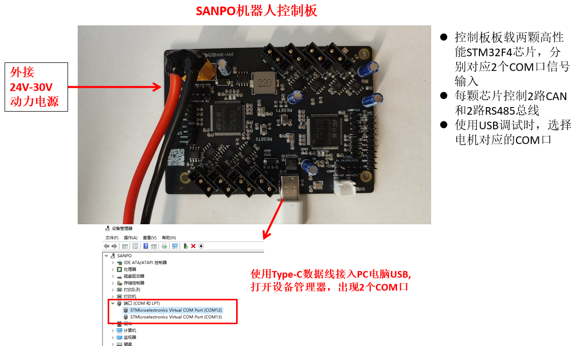
The SANPO robot integrated controller board Standard Version uses dual high-performance STM32 MCU control cores and provides a unified software development and interface usage model.
The board integrates 2 STM32 MCU modules.
One side of the joint chain is used as one bus channel and communicates with the corresponding STM32 MCU module.
One STM32 MCU module controls one side of the communication chain, and both modules together handle multi-channel bus communication and task scheduling.
Based on the MIT Cheetah SPINE design approach, multi-channel motor control can meet high-frequency control requirements.
UART, IIC, ADC, and similar peripheral interfaces are distributed across the two STM32 MCU modules for sensor expansion and data acquisition.
Firmware download and debugging are supported through the SWD interface, with SWD 1 and SWD 2 corresponding to the two STM32 MCU modules.
When using SPI, chip-select signals can be used to address the two STM32 MCU modules independently.
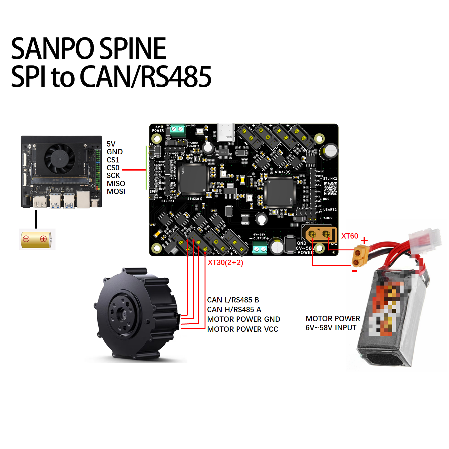
Power Architecture
The board supports a 6V~58V motor system power supply. The control system can be powered from USB, a 5V terminal, or host 5V GPIO, and the board can provide 6V~58V and 3.3V power outputs. It provides 4 independent CAN channels and 4 independent RS485 channels for mixed-bus debugging, functional validation, and rapid development.
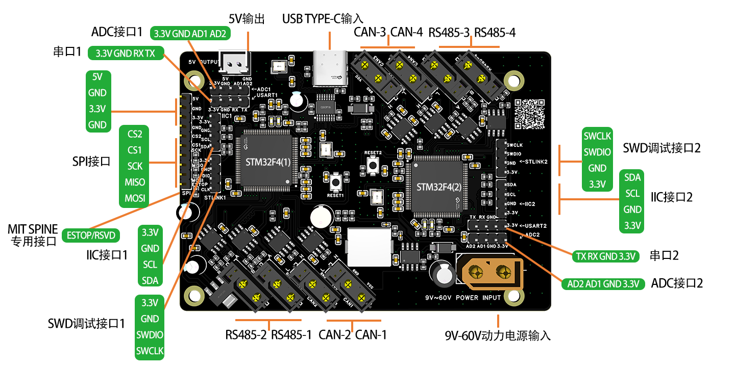
Board Interface Diagram
Before wiring, refer to the actual board silkscreen and connector definitions.
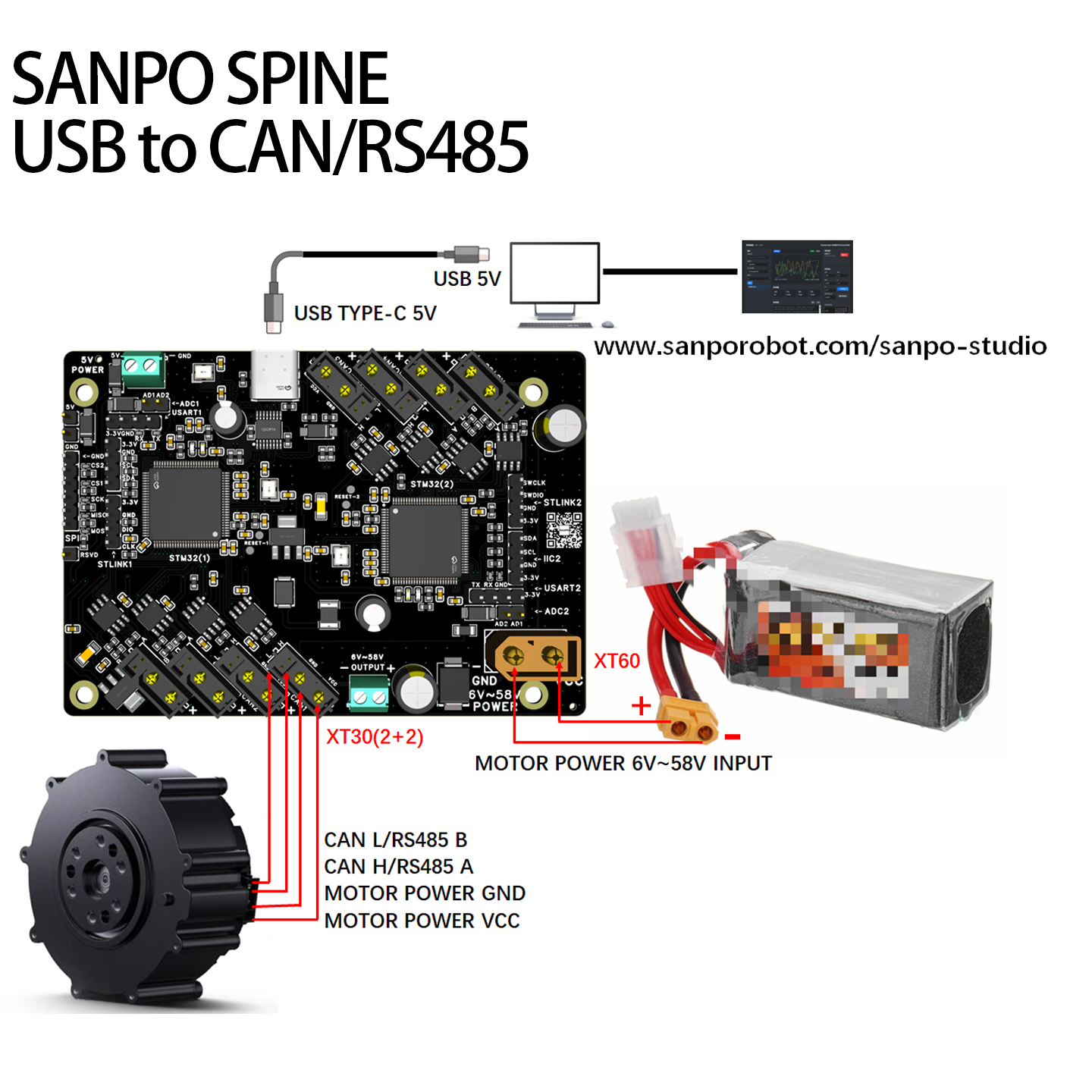
USB Connection (PC / Host Debugging)
USB is suitable for PC debugging, online control, and functional verification. After connecting through USB, you can use the corresponding motor debugging software to test CAN or RS485 motor communication.
USB is a host-side connection method.
Select the CAN or RS485 bus wiring method based on the motor protocol.
It can be used together with SANPO Studio or the motor vendor’s official debugging tool.
SPI Connection (Host Controller Examples)
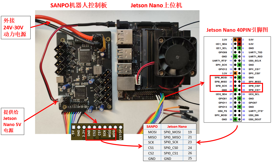
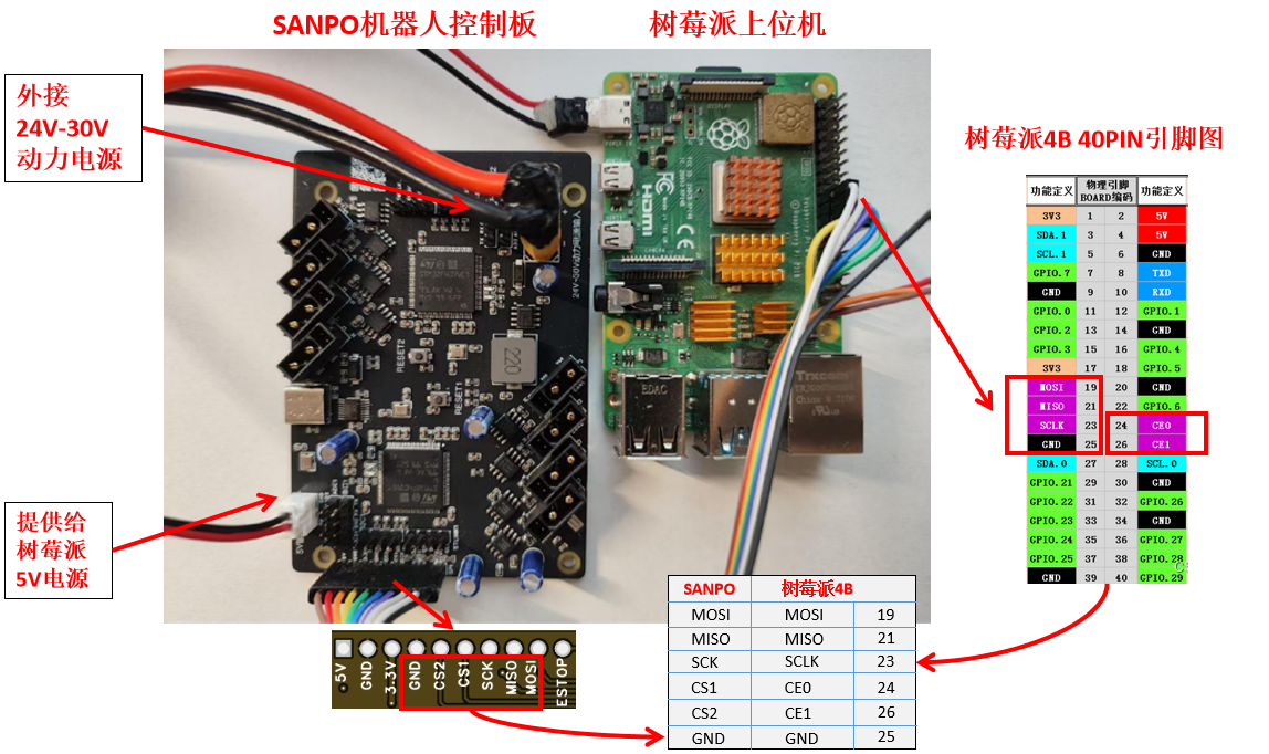
SPI is suitable for high-speed communication between the host controller and the board, for example with Jetson Nano, Raspberry Pi, and similar host platforms.
When SPI is used as the control input, CS1 maps to STM32 MCU (1) and CS2 maps to STM32 MCU (2).
Jetson Nano and Raspberry Pi are wiring examples only. Other host controllers can use the same method as long as the SPI pin mapping is consistent.
Select the CAN or RS485 device-side connection method based on the actual motor protocol.
1. Jetson Nano Wiring
2. Raspberry Pi Wiring
Debugging Tools
Choose the corresponding tool based on the motor type and debugging method:
SANPO motor debugging tool (supports multiple standard joint motors): Sanpo Studio Motor Tools
Xiaomi official motor tool (USB to CAN): Xiaomi CyberGear Tool
Unitree official motor tool (USB to RS485): Unitree GOM8010 Tool
Notes:
The CyberGear tool may fail to start if its installation path contains Chinese characters.
When using official motor debugging tools, make sure the wiring method and motor protocol type match.
If you need a unified tool for multiple standard joint motors, start with SANPO Studio.
Protocols and Example Code
The Standard Version supports USB, SPI, and UART as host-side control methods, and can connect to CAN / RS485 bus joint motors.
CAN Bus Control
Related pages:
RS485 Bus Control
Related pages:
Offline Execution
Related page:
Firmware and Secondary Development
For custom firmware, protocol extensions, or sensor integration, it is recommended to start from the official SANPO firmware.
Official firmware (customizable): STM32CubeIDE project
MIT Cheetah SPINE firmware (for study and compatibility reference): MBED STUDIO project
When using MIT Cheetah SPINE firmware, keep the following in mind:
It is better suited as a compatibility reference or learning resource than as the default production firmware.
It does not support USB or sensor integration.
It does not fully cover all capabilities of the current Standard Version.
For production projects or sensor integration, the official SANPO firmware is recommended.
For firmware update details, see Firmware Update:
Connect STLINK to the SWD interface of each onboard STM32 MCU.
Flash the latest firmware using STM32CubeProgrammer.
The two STM32 MCUs must be flashed separately.
Usage Notes
Select the CAN or RS485 motor bus type based on the actual motor protocol.
Confirm the power method and wiring plan before use.
If you need sensor integration or a stable foundation for secondary development, use the official SANPO firmware.
In SPI mode, the two chip-select lines correspond to the two STM32 MCUs. Make sure the host-side chip-select configuration is correct.
Always follow the board silkscreen and actual connector definitions for wiring and power input.