Get Started
The SANPO SPINE robot integration board connects a computer or host controller (such as a Raspberry Pi or Jetson) to CAN, CAN FD, and RS485 devices or joint motors. It can control four independent CAN/CAN FD channels and four independent RS485 channels through USB and SPI.
This guide applies to the V8 upgraded version (STM32G-series MCUs). For the V4 standard or isolated versions (STM32F-series MCUs), see the V4 User Guide.
In addition to the standard V4 features, V8 adds FDCAN, SocketCAN, CANgaroo, RS485 serial passthrough, and other functions.
Tip: This guide has been prepared to be friendly to AI. After connecting the computer or host controller, power supplies, and motors, you can provide this guide and the example programs to an AI assistant to develop your control logic.
Initial Connection and Power
Controlling FDCAN/CAN/RS485 Devices over USB
1. Hardware wiring and power
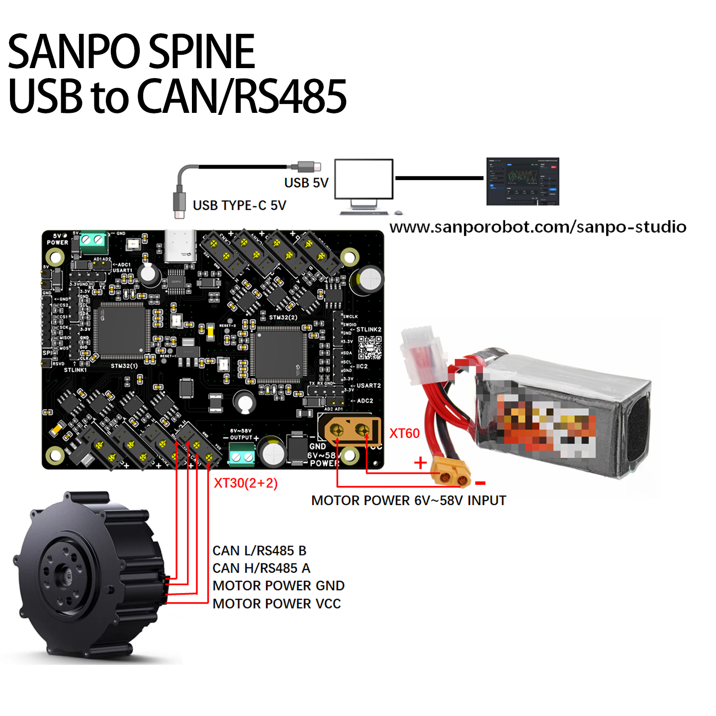
Connect the XT60 to the motor power supply, connect the XT30 (2+2) to the motor CAN/RS485 integrated interface, and connect USB Type-C to a computer or host controller (Jetson, Raspberry Pi, or another controller) to power the SANPO SPINE integration board.
2. Open the online debugging tool
Open SANPO Studio.
Select the appropriate option:
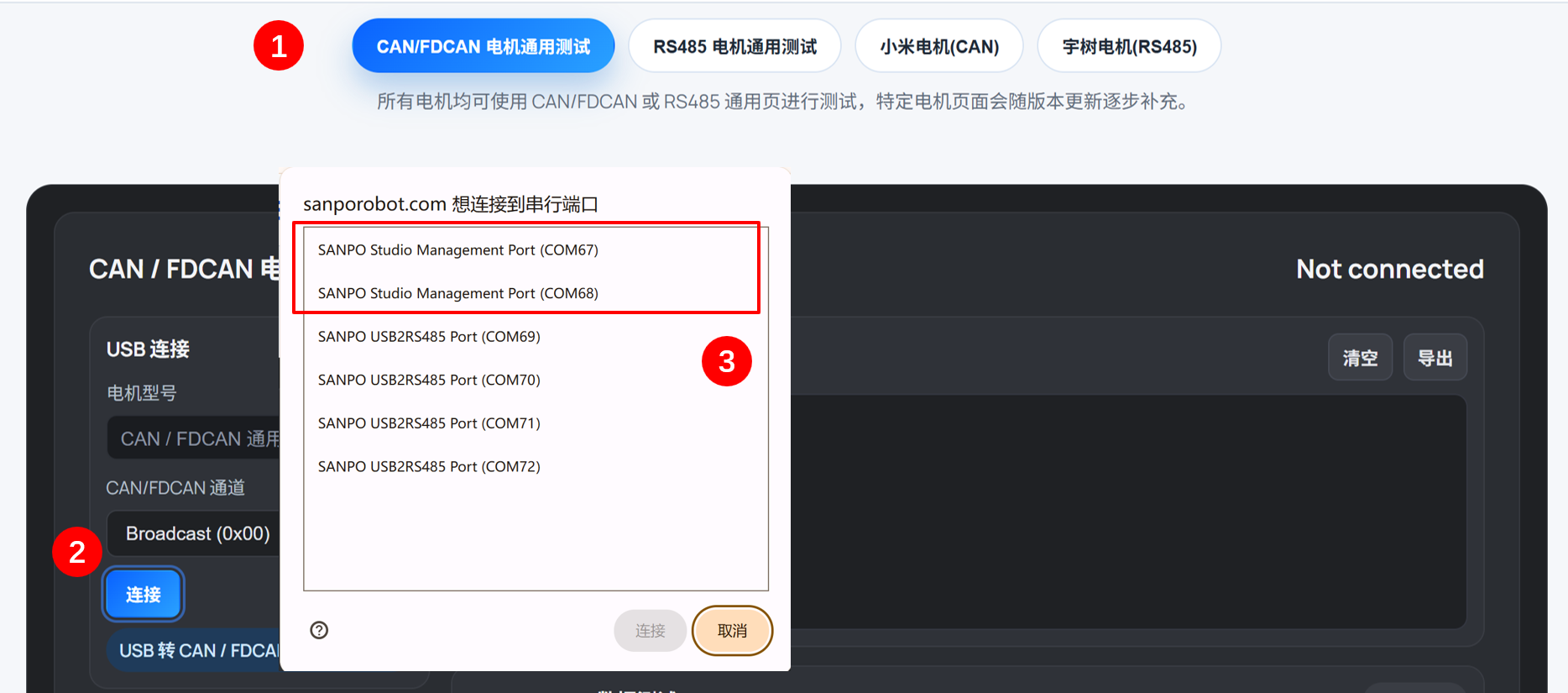
Generic FDCAN/CAN Motor Test,Generic RS485 Motor Test,CyberGear Motor Test, orUnitree Motor Test.Click
Connect.In the port selection dialog, select
SANPO Studio Management Port. SANPO Studio uses protocol mode, so select a management port rather than an RS485 passthrough port (used for passthrough mode).
Send
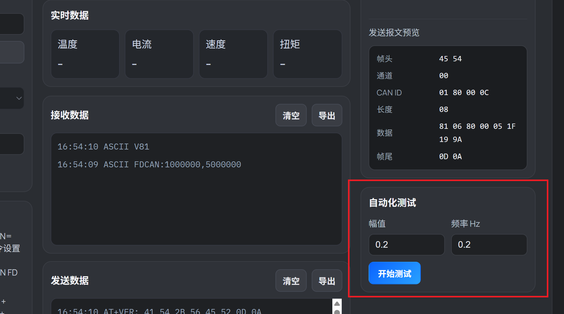
FDCAN/CAN/RS485data for testing.
For SANPO Motor, Xiaomi CyberGear, and Unitree GM8010 motors, you can select the automation test in the lower-right corner to run a low-speed sinusoidal motion and observe smoothness and control accuracy.
3. Other control methods
SANPO SPINE supports both passthrough mode and protocol mode for different use cases.
Protocol mode: Add the specified header and trailer when sending data. SANPO SPINE receives the frame, removes the header and trailer, and forwards the original data to the FDCAN/CAN/RS485 device.
Passthrough mode: Forward the original data directly to the FDCAN/CAN/RS485 device without any processing by SANPO SPINE.
In addition to using SANPO Studio in protocol mode, you can use other tools and passthrough mode, including the original host software for Unitree and Xiaomi motors.
The following methods work with joint motors from all brands; choose the one that best fits your workflow.
Control mode |
Documentation |
Debugging tool |
Example program |
Data interface |
|---|---|---|---|---|
USB to RS485 passthrough |
Serial assistant |
|||
USB to RS485 protocol mode |
Unitree GM8010 motor example |
|||
USB to FDCAN/CAN passthrough |
Xiaomi CyberGear motor example (SocketCAN) |
|||
USB to FDCAN protocol mode |
||||
USB to CAN protocol mode |
SANPO Motor control example |
Controlling FDCAN/CAN/RS485 Devices over SPI
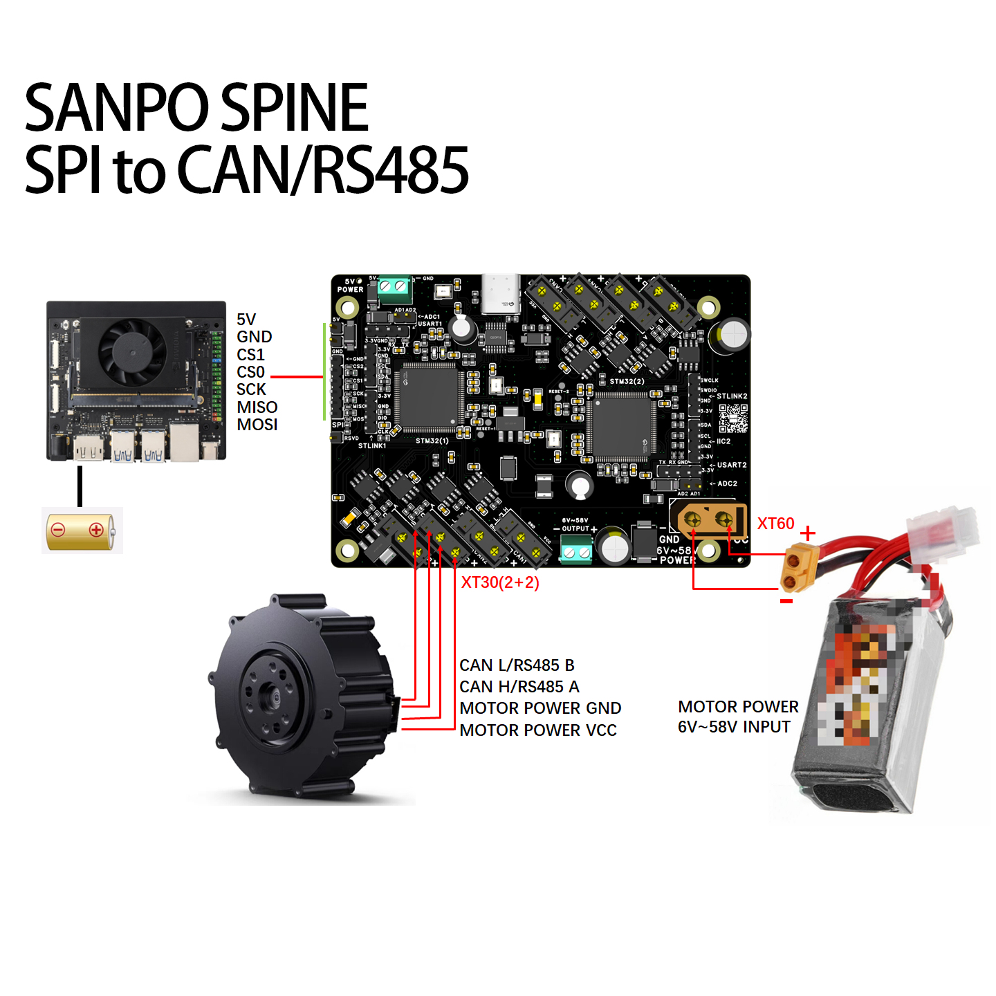
1. SPI wiring and power
Connect the XT60 to the motor power supply, connect the XT30 (2+2) to the motor CAN/RS485 integrated interface, connect the SPI (MOSI/MISO/SCK/CS0/CS1) header to the SPI interface of a host controller (Jetson, Raspberry Pi, or another controller), and connect the 5 V header to the host controller to power the SANPO SPINE integration board.
Tip: USB can still power the integration board in addition to the 5 V header. Keeping the GND connection from the 5 V header to the host controller is recommended for stable high-speed SPI signals.
See the Raspberry Pi SPI wiring example and the Jetson Nano SPI wiring example.
2. SPI protocol mode
SPI uses protocol mode. Add the specified header and trailer when sending data. SANPO SPINE removes them after reception and forwards the original data to the FDCAN/CAN/RS485 device.
See the SPI to CAN protocol guide and examples.
See the SPI to FDCAN protocol guide and examples.
See the SPI to RS485 protocol guide and examples.
Other Functions
Offline batch execution: save and automatically execute a group of motor commands.
Official firmware extension development: continue development based on the official firmware while retaining its communication forwarding functions and adding sensors or other peripherals.
Custom firmware development: completely customize all functions based on the hardware configuration framework.
Interfaces and pin definitions: STM32 peripheral pin assignments.
Firmware update: update both STM32 MCUs with ST-LINK.
Important: Do not perform a full-chip erase when updating or customizing the SANPO SPINE integration-board firmware. A full-chip erase deletes factory identification, saved communication parameters, and offline batches.
FAQ
Symptom |
Solution |
|---|---|
Why are six serial ports shown after USB is connected? |
Two of the six serial ports are management ports for USB protocol mode, and four are RS485 ports for RS485 passthrough. |
No response after sending a command through a management port |
Try the other management port. The two ports correspond to CAN/RS485-1/2 and CAN/RS485-3/4, but enumeration order does not correspond to the board silkscreen. Determine the mapping on first use; it remains stable on subsequent connections. |
SocketCAN CANX numbering does not match the board |
|
Tip: Linux and Windows serial-port and network-interface enumeration can be identified automatically during production. Factory initialization can record the mapping in a configuration file.
Appendix 1: USB/SPI Connection and Serial/Network Selection
USB to RS485 Passthrough
After connecting USB to a computer or host controller, four SANPO USB2RS485 serial ports appear. Each port corresponds to one RS485 channel. The baud rate and other serial parameters used when opening the port are synchronized to the RS485 bus, and data is passed through unchanged.
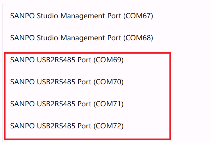
See How to identify RS485 serial ports on Windows and How to identify RS485 serial ports on Linux.
USB to RS485 Protocol Mode
Add the specified header and trailer around the original data. SANPO SPINE removes them and forwards the original data to the RS485 device. Protocol mode uses two SANPO Studio Management Port serial ports, one for each onboard STM32 MCU; each MCU controls two RS485 channels.
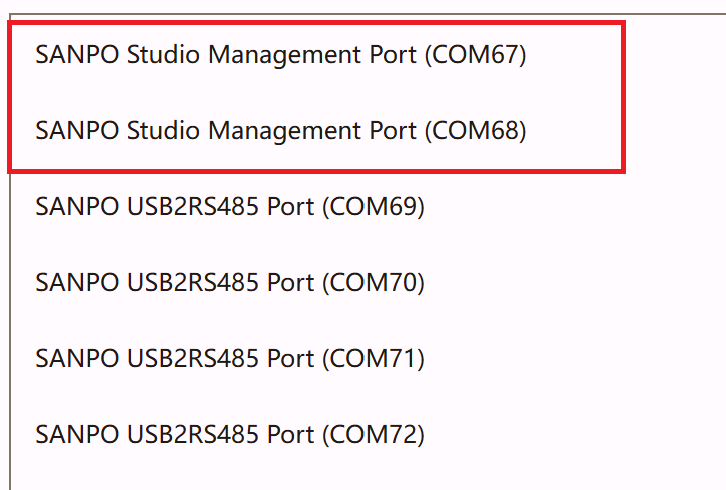
See How to identify RS485 serial ports on Windows and How to identify RS485 serial ports on Linux.
USB to FDCAN/CAN Passthrough
Use Linux SocketCAN, PythonCAN, CandleLight, or other compatible methods. The image below shows four CAN channels viewed with SocketCAN on Linux (the Linux default names are can0, can1, can2, and can3).

USB to FDCAN/CAN Protocol Mode
Add the specified header and trailer around the original data. SANPO SPINE removes them and forwards the original data to the FDCAN/CAN device. Protocol mode uses two SANPO Studio Management Port serial ports, one for each onboard STM32 MCU; each MCU controls two CAN/FDCAN channels.
See How to identify RS485 serial ports on Windows and How to identify RS485 serial ports on Linux.
Appendix 2: Identifying Management and RS485 Passthrough Ports on Windows
Open SANPO Studio on Windows and click Connect. The browser serial-port chooser displays the port names directly:
Select
SANPO Studio Management Portfor SANPO Studio or protocol mode.Select
SANPO USB2RS485 Portin your serial application for raw RS485 passthrough.
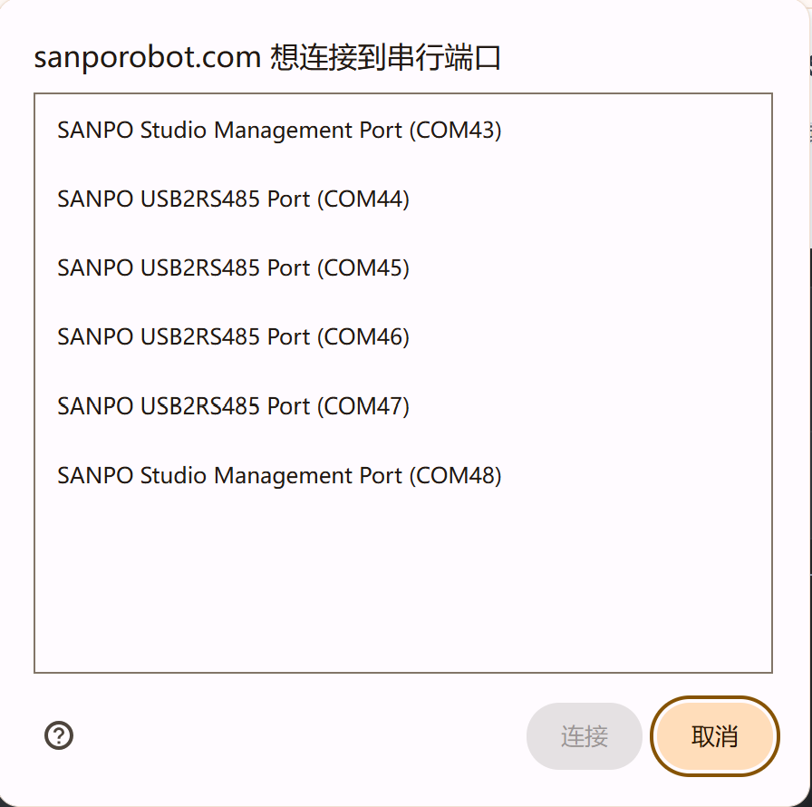
The SANPO Studio connection window distinguishes the port roles, but it cannot determine which port corresponds to the board’s physical RS485-A/B/C/D connector. On first use, connect or test one channel at a time and save the port-to-physical-interface mapping in your host application.
Appendix 3: Identifying Management and RS485 Passthrough Ports on Linux
On Linux, run identify_sanpo_serial_ports_v8.py from demo/rs485. The script only reads USB serial-port information; it does not open a port or transmit data:
cd demo/rs485
python3 -m pip install pyserial
python3 identify_sanpo_serial_ports_v8.py
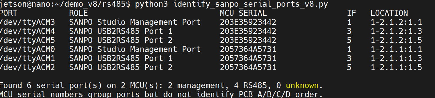
MCU SERIAL groups one management port with the two RS485 passthrough ports of the same MCU. Port 1 and Port 2 identify the two RS485 channels within that MCU only. Neither the USB serial number nor the /dev/ttyACM* number can determine the board’s A/B/C/D order automatically, so record the physical mapping after the first wiring test.
Use JSON output when another program needs to process the result:
python3 identify_sanpo_serial_ports_v8.py --json
Appendix 4: USB Protocol-Mode Frame Headers
Protocol mode uses two management serial ports for USB-to-CAN/FDCAN/RS485 communication. The frame headers are defined below (passthrough mode has no wrapper and transfers raw data directly):
Header |
Hexadecimal |
Purpose |
|---|---|---|
|
|
Classic CAN standard frame |
|
|
Classic CAN extended frame |
|
|
CAN FD standard frame |
|
|
CAN FD extended frame |
|
|
RS485 frame wrapper |
Appendix 5: Jetson Nano SPI Wiring Example
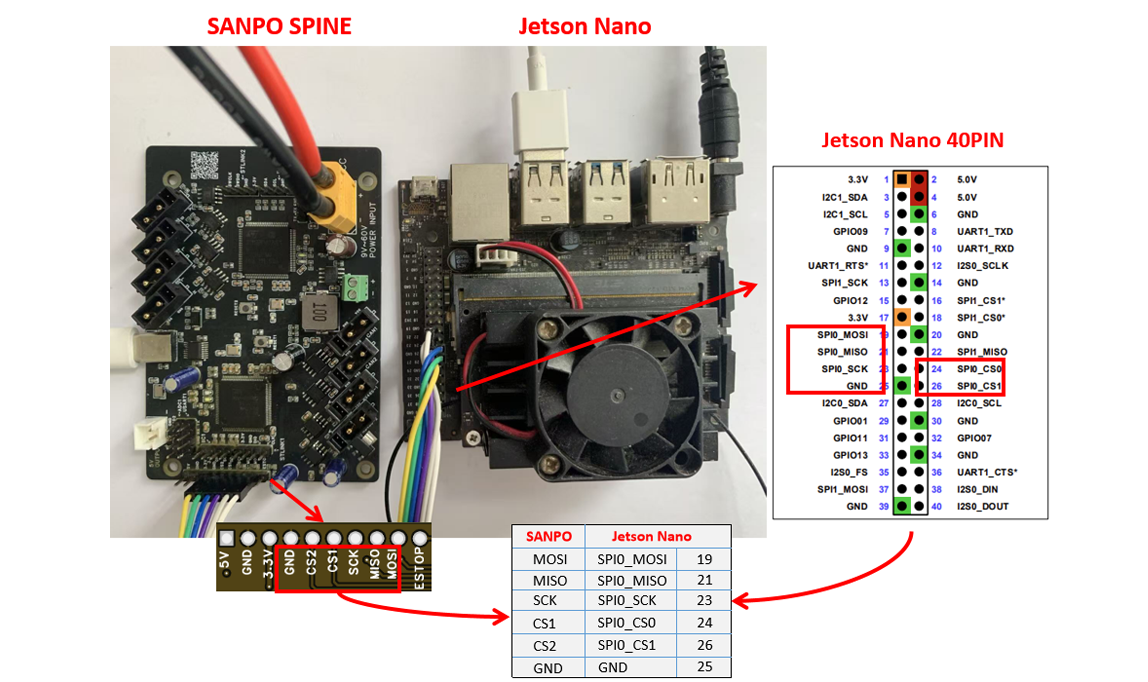
The GND shown below must be connected. Even when USB powers the SANPO SPINE integration board, keep the GND connection between the Jetson and the board SPI interface. Connecting two GND wires to the Jetson is recommended.
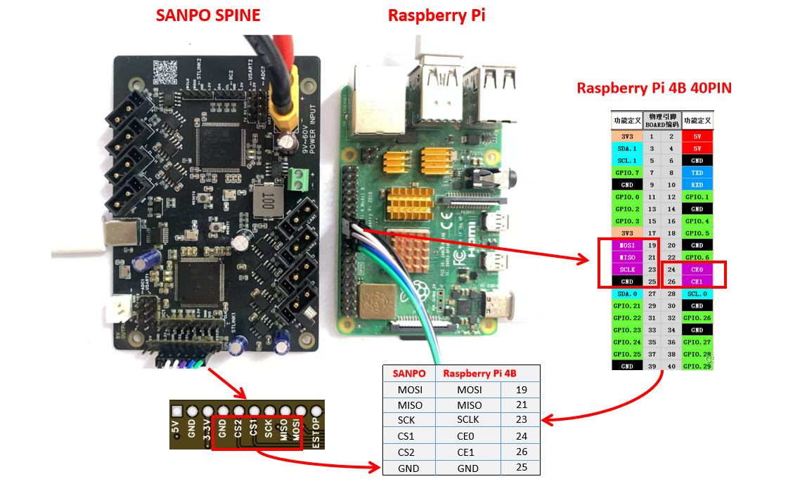
Appendix 6: Raspberry Pi SPI Wiring Example
The GND shown below must be connected. Even when USB powers the SANPO SPINE integration board, keep the GND connection between the Raspberry Pi and the board SPI interface. Connecting two GND wires to the host is recommended.