Developing Custom Firmware
Custom firmware examples are intended for users who want to implement their own CAN, RS485, and device-control logic. Each example already contains the STM32F407 pin assignment and basic peripheral configuration and can be opened directly in Keil 5.
These examples do not include the V47 factory USB/SPI to CAN/RS485, SocketCAN, or offline-execution functions. To keep those functions and only add I2C, ADC, UART devices, or application code, use Developing with the SANPO Firmware.
Choose an Example
Requirement |
Recommended project |
|---|---|
Control CAN standard-frame devices with custom firmware |
|
Control CAN extended-frame devices with custom firmware |
|
Control RS485 devices with custom firmware |
|
Keep SANPO factory USB/SPI-to-CAN/RS485 control functions and only add peripherals |
Download: F407 custom firmware examples
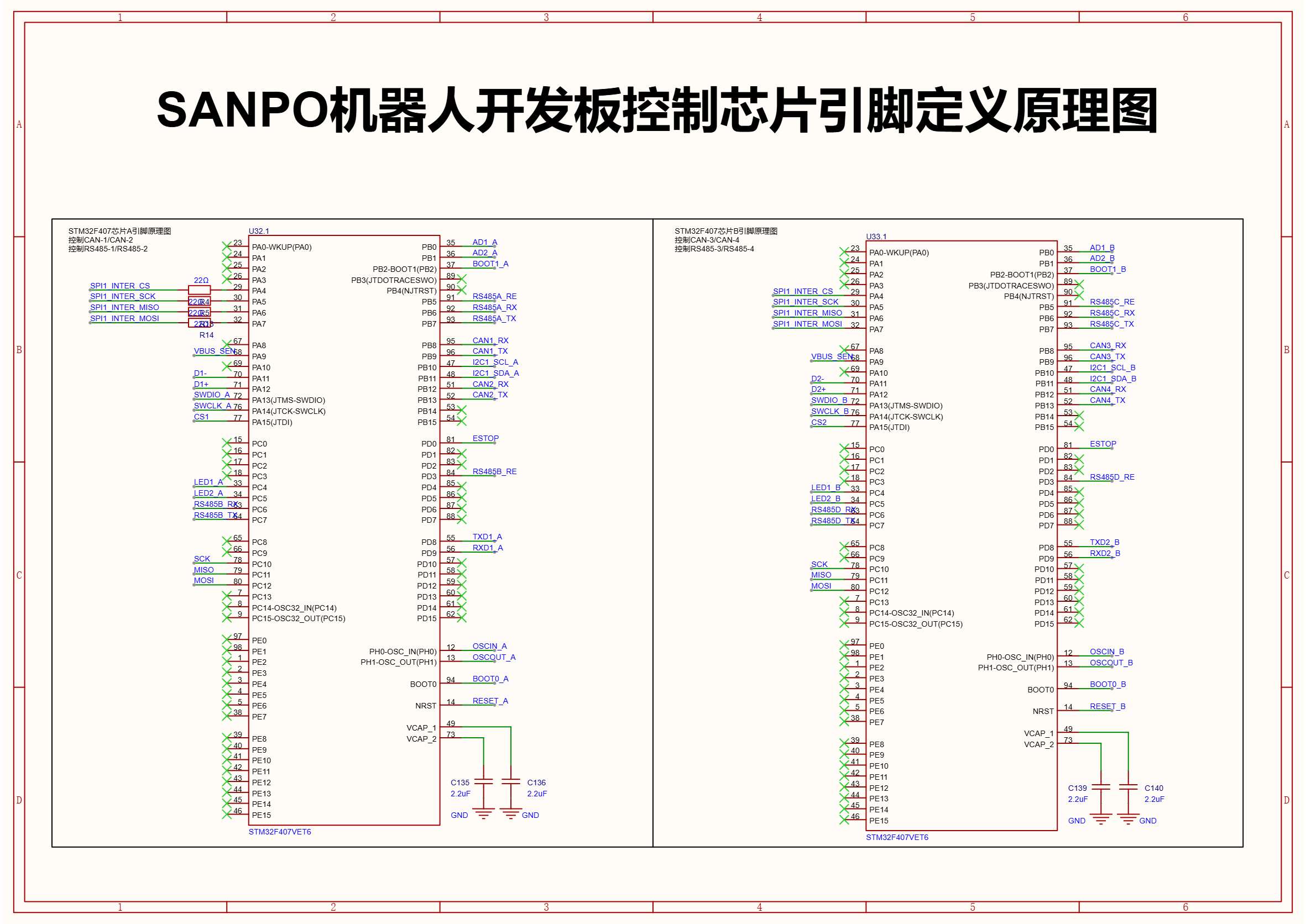
The Same Firmware Works on Both MCUs
The two STM32F407 devices use the same part and pin assignment. Each CAN or RS485 example therefore needs only one project. The same build can be programmed on either or both MCUs.
Programming connector |
Interfaces in the project |
Board interfaces |
|---|---|---|
MCU (1) SWD |
CAN1/CAN2, RS485-A/RS485-B |
CAN-1/CAN-2, RS485-1/RS485-2 |
MCU (2) SWD |
CAN1/CAN2, RS485-A/RS485-B |
CAN-3/CAN-4, RS485-3/RS485-4 |
Keil Environment
All three examples use:
Keil MDK 5;
Arm Compiler 5.06 update 7;
Keil::STM32F4xx_DFP3.1.1;ST-LINK.
Open the .uvprojx file in an example and press F7 to build. Program through the ST-LINK (SWD) connector. Do not perform a full-chip erase, because it removes board factory information and data saved by the factory firmware.
Each example includes an .ioc file. You may use STM32CubeMX to change basic peripherals, but back up the project before generating code. Afterwards, verify CAN/RS485 settings, direction control, user code, and Keil project settings again.
CAN Standard-Frame Example
Download: CAN standard-frame example
At 1 Mbit/s, the project sends this standard frame once per second on both CAN channels managed by the current MCU:
ID   = 0x141
Data = 9A 00 00 00 00 00 00 00
USART3 uses 115200-8-N-1 and prints transmitted and received CAN IDs, lengths, and data.
The default frame only demonstrates transmission and may not be valid for your device. Update the CAN ID and data according to the device protocol before connecting a motor or actuator. See the README inside the example for the exact source locations and Keil steps.
CAN Extended-Frame Example
Download: CAN extended-frame example
This project demonstrates CyberGear extended-frame control with the following defaults:
Item |
Default |
|---|---|
CAN bitrate |
1 Mbit/s |
Motor ID |
12 |
Motion amplitude |
0.2 rad |
Motion frequency |
0.2 Hz |
Command period |
10 ms |
Kp / Kd |
10.0 / 0.5 |
After startup, the example configures the mode, enables the motor, and begins oscillating. For the first test, lift the output shaft, clear the motion area, and be ready to disconnect motor power. By default, commands are sent on both CAN channels managed by the current MCU. When testing one channel, connect only the target motor or change the send function.
See the README inside the example for parameter locations, debug output, and Keil steps.
RS485 Example
Download: RS485 example
This project demonstrates a 17-byte command and 16-byte feedback format used by Unitree GO-M8010-class motors. Defaults are:
Item |
Default |
|---|---|
RS485 |
4 Mbit/s, 8-N-1 |
Motor ID on both channels |
1 |
Target-position increment |
0.2 rad |
Kp / Kd |
2.5 / 0.12 |
Debug UART |
USART3, 115200-8-N-1 |
Both RS485 channels may drive a motor after programming. Secure the motor, lift the output shaft, and check A/B wiring and power before the first test. USART3 forwards the 16-byte feedback as binary data, so view it in hexadecimal mode.
The example uses blocking transmission and reception to keep the code easy to understand. It is not intended as high-rate production code. For a product, use interrupts or DMA as required by the control cycle and complete continuous-operation and packet-loss testing.
Checks After Development
At minimum, verify:
Keil reports
0 Error(s).CAN bitrate or RS485 settings match the device.
The physical interface mapping is correct when programming either MCU.
The device receives valid commands and returns valid feedback.
Motor motion limits and protection parameters are safe.
Long-duration operation has no unexpected resets, communication interruptions, or obvious packet loss.