Factory Authentication Recovery
This guide addresses factory firmware failures caused by accidentally erasing factory authentication information with Full chip erase, Mass erase, or an equivalent full-chip erase operation. Custom firmware does not depend on this authentication information and is unaffected.
The board contains two STM32F407 MCUs, identified in this guide by the PCB labels STM32(1) and STM32(2). A single USB Type-C connection links both MCUs through the onboard USB HUB, so COM port numbers, names, and Device Manager order do not identify the MCU number.
This procedure first programs UID Reader only onto the MCU labeled STM32(1). The only MCU returning UID Reader information is therefore STM32(1). UID Reader is then programmed onto STM32(2), and the new UID that differs from the first one identifies STM32(2). These two labeled UIDs must be used throughout recovery and verification.
Important: Do not use
Full chip erase,Mass erase, any equivalent full-chip erase operation, or modify Option Bytes at any point in this procedure.
Downloads
Software or file |
Purpose |
Download |
|---|---|---|
UID Reader V3 HEX |
Read the hardware UID and inspect Sector 7 status |
|
UID Reader checksums |
Verify the UID Reader BIN/HEX files |
|
UartAssist |
Windows serial terminal |
|
STM32CubeProgrammer |
Program and verify firmware through ST-LINK |
|
Spine V4 V47 factory firmware |
Program after authentication is restored and verified |
The STM32_1_<UID>_sector7.hex and STM32_2_<UID>_sector7.hex files returned by customer service contain device-specific authentication information. They cannot be downloaded from the public repository and must not be replaced with files for another board.
1. Prepare the Tools
Download and extract
UartAssist.zip, then runUartAssist 5.0.2.exe. Installation is not required.Download, extract, and open STM32CubeProgrammer.
Download
sanpo_v4_uid_reader.hex.Prepare an ST-LINK and a USB data cable, and locate the
STM32(1)andSTM32(2)labels on the PCB.Connect ST-LINK only to the MCU currently being operated on. Keep USB Type-C connected.
2. Read and Label the Hardware Information of Both MCUs
2.1 Read STM32(1) First
Following the PCB label, connect ST-LINK to the SWD connector for
STM32(1)and power the board.In the upper-right corner of STM32CubeProgrammer, select
ST-LINKand use:Port:
SWDFrequency: keep the default; reduce it if the connection is unstable
Reset mode: start with the default; use
Under Resetif connection fails
Click
Connectand confirm that the log identifies an STM32F407.Open
Erasing & Programmingand selectsanpo_v4_uid_reader.hex. The HEX file already contains address0x08000000; do not enter an address manually.Select
Verify programmingand clickStart Programming. After success, clickDisconnect, then power-cycle or reset the board.Wait for USB HUB enumeration. One COM port may appear, or two may appear if the other MCU’s existing firmware still runs. In UartAssist, check every currently available COM port using:
Baud rate:
115200Data bits:
8Stop bits:
1Parity:
NoneFlow control:
NoneSend and receive mode: text/ASCII, not HEX
Line ending:
CRLF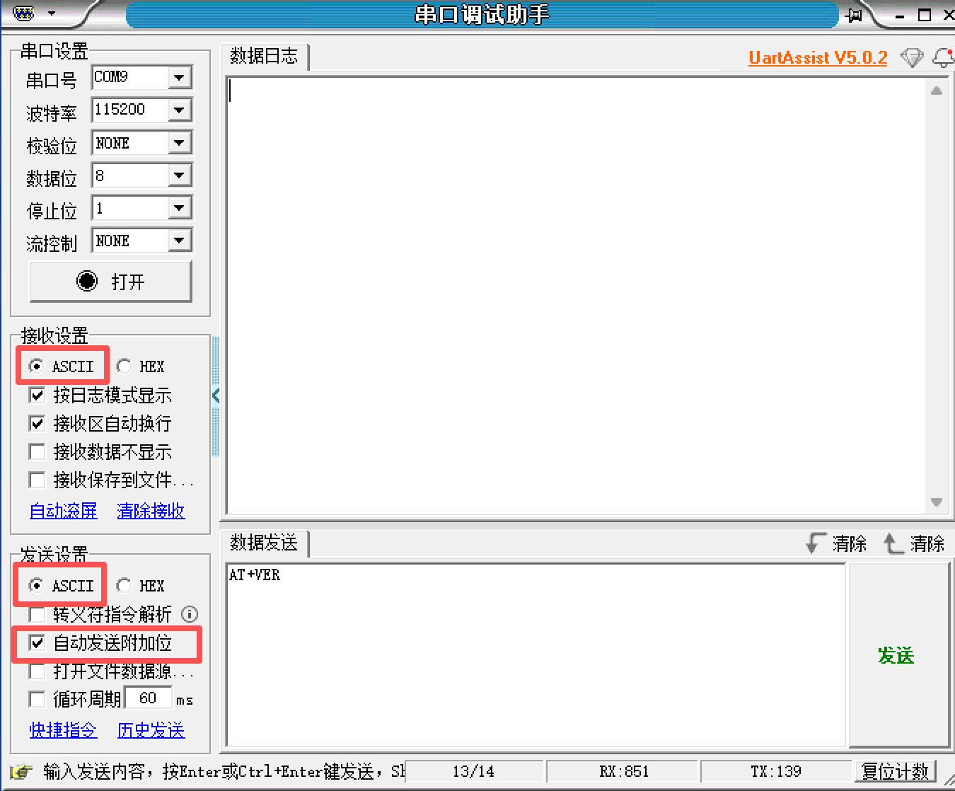
Send
AT+HWINFOto each port. Do not type the literal characters\r\n. At this point, onlySTM32(1), which is running UID Reader, returns a line in this format:
SANPO_V4_HWINFO,V=3,UID=XXXXXXXX-XXXXXXXX-XXXXXXXX,SECUID=FFFFFFFF-FFFFFFFF-FFFFFFFF,DEVID=413,REVID=XXXX,FLASHKB=512,SECTOR7=BLANK
Copy the complete line and label it clearly as
STM32(1). Do not save or rely on the current COM number, because its number and order may change after reconnecting or resetting the board.
If no port returns SANPO_V4_HWINFO,V=3, or two different V3 responses appear, stop the procedure. Check the programming target and log, then contact customer service.
2.2 Read STM32(2)
Move ST-LINK to the SWD connector identified by the
STM32(2)PCB label.Program and verify
sanpo_v4_uid_reader.hexin the same way as for STM32(1), then power-cycle or reset the board.Use UartAssist to open every COM port enumerated by the USB HUB and send
AT+HWINFO.You should now obtain two different
SANPO_V4_HWINFO,V=3lines:The line whose
UIDmatches the first saved value isSTM32(1).The new
UID, which differs from the first value, isSTM32(2).
Copy the complete new line and label it clearly as
STM32(2).
If you do not obtain two different UIDs, do not guess the relationship between an MCU and a COM port. Recheck the second programming operation and all COM ports.
2.3 Send the Information to Customer Service
Send both complete original lines and retain the following labels:
STM32(1): SANPO_V4_HWINFO,V=3,UID=........-........-........,SECUID=........-........-........,DEVID=413,REVID=....,FLASHKB=512,SECTOR7=....
STM32(2): SANPO_V4_HWINFO,V=3,UID=........-........-........,SECUID=........-........-........,DEVID=413,REVID=....,FLASHKB=512,SECTOR7=....
3. Check the Recovery Package from Customer Service
The recovery directory should contain:
STM32_1_<UID>_sector7.hex: only for the MCU identified by theSTM32(1)PCB labelSTM32_2_<UID>_sector7.hex: only for the MCU identified by theSTM32(2)PCB labelspine_v4_official.binmanifest.jsonSHA256SUMS.txtCustomer recovery instructions
Both Sector 7 filenames contain the MCU position label and that MCU’s hardware UID. Before programming, confirm that the UID in each filename exactly matches the corresponding UID saved in Section 2. Never exchange the two files.
UID Reader status fields mean:
UID: the current MCU’s actual hardware UID.SECUID: the UID stored in Sector 7; an empty area normally contains allFcharacters.BLANK: the Sector 7 authentication block is empty.INVALID: the Sector 7 format, length, end marker, or CRC is invalid.UID_MISMATCH:SECUIDdiffers from the current MCU’s actualUID, which means the device-specific HEX file was programmed onto the wrong MCU.UID_MATCH:SECUIDmatches the actualUID, and the format and CRC are valid.
4. Restore and Verify STM32(1)
Following the PCB label, connect ST-LINK to the SWD connector for
STM32(1).Connect in STM32CubeProgrammer, open
Erasing & Programming, and selectSTM32_1_<UID>_sector7.hex. The HEX file already contains address0x08070000; do not change the address.Select
Verify programmingand clickStart Programming. After success, disconnect and power-cycle or reset the board. UID Reader is still running at this point.Use UartAssist to query every currently enumerated COM port. Identify the
STM32(1)response by the hardware UID saved in Section 2, not by the COM number.All three conditions must be met:
UIDexactly matches the previously labeledSTM32(1)UID.SECUIDexactly matchesUID.SECTOR7=UID_MATCH.
Only after verification, reconnect STM32CubeProgrammer, select
spine_v4_official.binfrom the recovery package, manually enter download address0x08000000, keepVerify programmingselected, and start programming.
If UID_MISMATCH, INVALID, or an incorrect UID appears, do not continue with factory firmware. Save the UID Reader response and STM32CubeProgrammer log and contact customer service. Do not perform a full-chip erase.
5. Restore and Verify STM32(2)
Following the PCB label, move ST-LINK to the SWD connector for
STM32(2).Select
STM32_2_<UID>_sector7.hex, then program and verify it in the same way as for STM32(1).Before factory firmware overwrites UID Reader, query every currently enumerated COM port again. Identify the
STM32(2)response by the saved hardware UID and confirmUID=SECUIDandSECTOR7=UID_MATCH.Only after confirmation, program
spine_v4_official.binfrom the recovery package at0x08000000.
6. Final Verification
After both MCUs are complete, disconnect board power for 10 seconds and then power it again.
In UartAssist, open both COM ports enumerated by the USB HUB and send
AT+VERin text mode with aCRLFline ending. Confirm that both ports return the factory firmware version.Test CAN, RS485, SPI, and motor communication as required by the application.
AT+VER only confirms that the factory firmware is running. By itself, it does not prove that a Sector 7 file was programmed onto the correct MCU. Before programming the factory firmware, the UID Reader response must confirm UID=SECUID and SECTOR7=UID_MATCH.
If programming fails, a status is abnormal, or the factory firmware does not respond, stop the procedure. Save both labeled, complete SANPO_V4_HWINFO lines and the STM32CubeProgrammer log, then contact customer service.